- NMR Sample Preparation
- Experiment Preparation
- 1D 1H
- 1D 31P
- 1D WaterGate
- 2D Experiment Setup
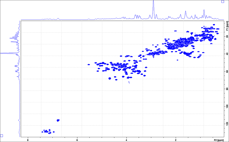
- 1H-15N HSQC
- 1H-13C HSQC
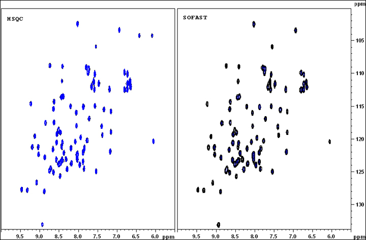
- 1H-15N SoFast-HMQC
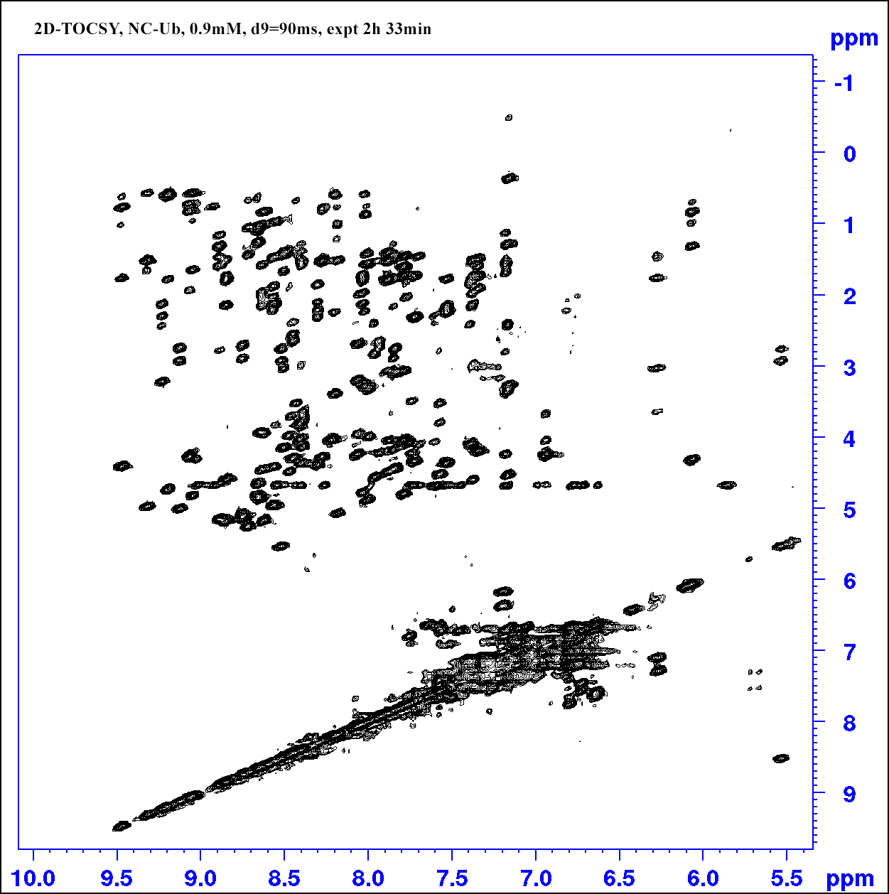
- 2D TOCSY
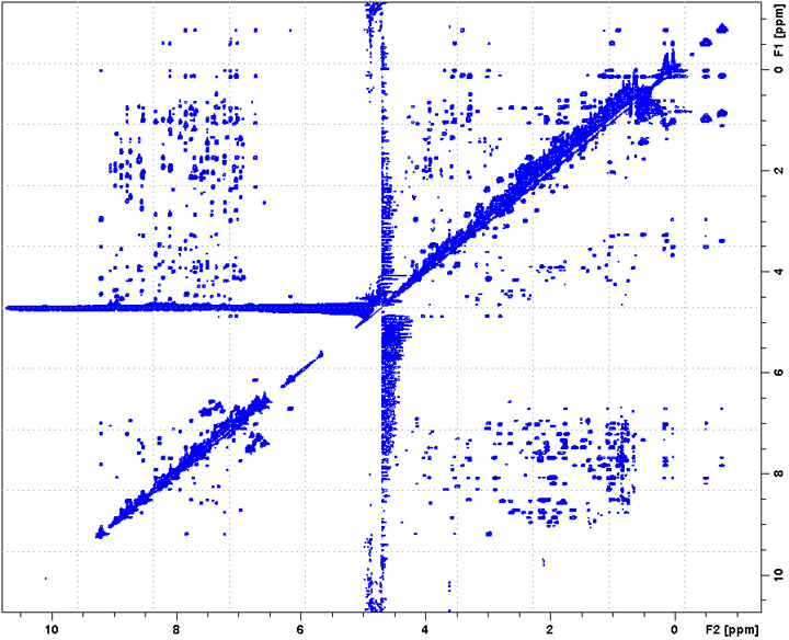
- 2D NOESY
- Triple Resonance Experiments
- Saturation Transfer Difference NMR
- BBFO probe experiments
- Non-Uniform Sampling (NUS)
NMR Sample Requirements and Preparation
- Sample Concentration Guidance for Cryoprobe NMR Measurements:
- Biomolecule samples. Prepare at least 0.05mM. Higher than 1 mM is prefered as long as solution viscosity does not increase significantly.
- Small molecule samples. About 3mM is sufficient for 13C direct NMR measurements on CP800, and 10mM for 13C measurements on CP600. High concentration is still encouraged since it will greatly reduce the experiment time. If a sample's MW is 200, 10mg/500uL gives 100mM concentration. Please note that for quantification, avoid preparing too high concentration which may cause baseline and lineshape issues.
NMR tube choices: If you have adequate amount of sample, use a regular NMR tube; If you have limited amount of sample, usage a shigemi NMR tube; If your sample has high salt concentration , use a 3mm NMR tube.
-
Sample volume should be a minimum of 250 uL for a Shigemi tube, 160uL for a 3mm/5mm tube, or 500 uL for a regular NMR tube. Insufficient volume may cause bad shimming result, and consequently spectra with poor resolution and line shape. In many cases the sample volume should weight more than the concentration for a good NMR measurement.
-
The NMR sample should be homogeneous, free of air bubbles and insoluble substances. High salt concentration and paramagnetic ions should be avoided if possible
-
High quality NMR tubes should be used at BioNMR facility, in particular on the 800 MHz spectrometer.
-
For volatile organic solvent, or long term use sample, sealing the sample NMR tube with parafilm is highly recommended.
-
For aqueous samples,
-
D2O concentration should be equal to or higher than 7%, and kept equal to or higher than 7% during a titration.
-
NaCN 0.02% is recommended for sample buffer to prevent bacterial growth and bio sample degradation.
-
Degasing the buffer or the sample to reduce the chance of forming air bubbles in the solution.
-
-
Labeling a NMR tube
- All samples should be labeled with brief sample information using a labeling tape.
- Do not write directly on the NMR tube since the ink can easily be erased by mistake.
- The labeling tape should be wrapped around the NMR tube, not in the shape of a flag.
-
Sample Spinners
- CP800: Use the white spinners for experiments below 50 Celcius. Use the cemramic spinners for experiments above 50 Celcius.
- CP600: Use the white spinners.
- NMR600: Use the blue spinners (for lower air flow probes).
Experiment Preparation
- Adjust temperature
- Type "edte" or go to temperature control window.
- Set the target temperature and wait for temperature equilibrium. Do not change air flow rate.
- To CP800, turn chiller power off if temperature is set high, and set chiller power to maximum if temperature is set low.
- Insert sample
- SampleCase system (CP800 and CP600)
- Place the sample NMR tube with its spinner in a well of the Carousel sample holder, and note the sample position number.
- In topspin, type the command "sx #", where the # is the sample position number. Alternatively you may press the blue button on the Carousel to rotate the sample to the injection position under the injection tube, then press the green Inject/Eject button to inject the sample.
- Type "sx ej" to eject a sample. Then you need to rotate it to the side of the injection position to take it out from the sample holder
- SampleMail System (NMR600)
- Put the sample NMR tube with its spinner in the sample-holder
- Close the loading compartment and the sample will be injected automatically.
- To eject a sample, type "ej", and wait till the sample NMR tube sit in the sample-holder. Open the compartment and carefully take out the NMR tube.
- Manual injection system
- Type "ej" or click “lift” button from the BSMS interface.
- Placing the sample NMR tube with its spinner at the openning on top of the magnet, and make sure the sample tube floats before completely releasing it.
- Type "ij" or click “lift” again to lower the sample into the magnet.
- When taking out a sample, do not forget to type "ij" at the end to lower the air flow.
- SampleCase system (CP800 and CP600)
- Lock
Type “lock” and choose the correct deuterated solvent that is with the sample. Contact the NMR facility manager if you can not find your solvent in the solvent table.
- shim
- To shim a NMR sample, it is advisable to run "rsh" first. Choose the latest 3D shim file in the format TS3D_MMDDYY.
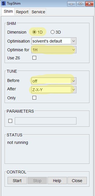
- Type "topshim gui", make sure the dimension is "1D", Optimise for is the nucleus to be detected, such as "1H".
- For a regular NMR tube, click on "start " to start shimming. Options: (1) Use a Tune Before option usually can improve the shimming result. Note that on CP600 spectrometer, only Tune After options works because of a different TopSpin version; (2) Include Z6.
- For a shigemi NMR tube, type in the command "topshim shigemi"
- Once shimming is complete, you can check the result on the Report page. If topshim didn't give satisfactory shimming result, final B0dev greater than 1Hz, you may want to troubleshoot why and then redo shimming.
- Tune and Match the probe
- First go to (work directory) a 1D zg data set; You may type "edasp" to check/set channels to be tuned.
- For probe with ATM device, type "atmm". Adjust tune and match of each nucleus, then exit.
- For probe without ATM device, type "wobb". Use the small driver to adjust corresponding match and tune knobs to current nucleus under the magnet. After one nucleus channel is finished, click on “SW” to switch to the next nucleus. At the end click "Stop" to finish the wobb procedure.
- Calibrate 1H 90° pulse
- In (work directory) zg experiment data set, you may use "pulsecal" to estimate 1H 90° pulse. Keep in mind that the estimate may be inaccurate when the sample buffer/solvent has high salt concentration or is viscous. Use the folloing steps to accurately determine 1H 90° pulse if needed
- In zg experiment data set, check default pL1/pLW1 value and set p1=4us, ns=1, ds=1.
- Then acquire FID by typing "zg". Fourier transform data by typing "ft". Phase the spectrum by typing “apk”.
- Reset p1 to 4x of the pulsecal result as a starting value, acquire FID by typing “zg”, and process the FID by typing “efp”.
- Keep adjusting p1 until you see a signal null, which corresponds to a 360° proton pulse. 1H 90° pulse should be 1/4 of the final p1. Alternatively you may use "paropt" to determine 1H 90° pulse.
- Determine O1P offset (for aqueous samples)
- Go to an 1D zgpr experiment (pulse program: zgpr). Or in an new experiment "rpar zgpr all".
- Type "eda", in the acquisition parameter window check and adjust td, ns, ds, sw.
- Type "ased", in the pulse program parameter window, enter calibrated p1 and pL1 values, check pL9 (should be greater than 50dB) and d1 2s.
- Type "gs"; in gs mode adjust O1P offset to achieve minimum FID area integral.
- Start the experiment by rga and zg; Process the FID by typing "efp" or “dfp”, and phase the spectrum when necessary. In general the SI should be set as 2X of TD in 1D
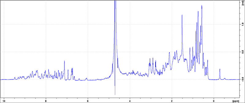
1D 1H with no water suppression
For samples requiring no solvent/water suppression, pulse program zg or zg30 can be used to run a simple 1D 1H experiment. The zg30 pulse needs much shorter relaxation delay d1 since the rotation angle is only 30 degrees. For quantitative NMR analysis, d1 needs to be set long enough to ensure full relaxation recovery.
1D 1H with water suppression
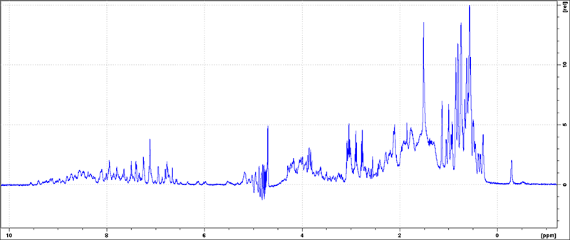
There are multiple methods to suppress water NMR signal. Excitation sculpting (zgesgp) and watergate (zggpwg) are effective in suppressing a large amount of water in a NMR sample, while pre-satuation methods such as zgcppr or zggppr are effective in suppressing trace amount of water in organic solvents.
-
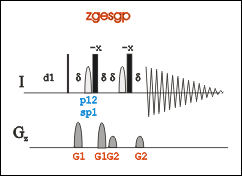 To create an new experiment, copy from an existing 1D zgesgp experiment (pulse program: zgesgp) using the command "edc". Or run "rpar ZGESGP all" to upload the parameter settings of the pulse in an new experiment.
-
Type eda to open the acquisition parameter window check and adjust td, ns, ds, sw.
- Check and adjust td, ns, ds, sw. TD in 1D 1H should be at least 16K. NS is dependent to the sample concentration. A 16 scan experiment is a good starting point, and use it as a reference to set up another 1D if signal intensity is not satisfactory. SW should be set wide enough to cover all the signals.
- Update O1, which should be the exact chemical shift of water signal of the current sample. O1 can be determined with a 1D zgpr experiment, or it can be found out with a one-scan proton zg or zg30 experiment.
- Type ased, in the pulse program acquisition parameter window, enter calibrated p1, pL1 values, and O1 which can be determined from 1D zgpr experiment. Or type "getprosol 1H A B" to set power related parameters. A is the determined 90 degree pulse length in µs, and B is the power leverl in dB.
- (Optional) Type gs, and in the gs mode adjust p12 to achieve minimum FID area integral.
- Run the command rga to estimate the receiver gain RG, adjust it if necessary, and start the experiment with the command zg;
-
Process the FID by typing “efp”, and phase the spectrum when necessary.
1D 31P
-
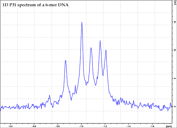
Type "rpar P31CPD" in a new data set, or use "edc" command to copy from an exisiting 1D 31P experiment. Another option is "rpar P31" depending on decoupling choice.
-
Use "getprosol" command to load the default phosphorous power parameters.
-
In the acquisition parameter window check and adjust td, ns, ds, sw, d1.
-
Estimate receiver gain using command rga, and then start the experiment using commandzg ;
-
Process the FID by typing “efp”, and phase the spectrum when necessary.
1D Watergate with 15N Decoupling Option 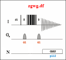
-
Copy an existing 1D experiment (pulse program: zgwg.df) by typing “edc”.
-
Type eda, in the acquisition parameter window check and adjust td, ns, ds, sw, O1P and O2P.
-
Type ased, in the pulse program parameter window, enter calibrated p1 and pL1 values; set pcpd2 220 us and corresponding pL12 12 dB if applying decoupling. Otherwise pL12 should be 120 dB.
-
Start the experiment by rga and zg;
-
Process the FID by typing “dfp”, and phase the spectrum when necessary.
General steps in setting up a 2D experiment.
- Creating a data set
- Use command "edc" to generate a new experiment set from the currently displayed experiment.
- Or, use "rpar" command to read from an existing data set. For instance, "rpar HSQCETFPF3GP" will create a new 1H-15N HSQC experiment.
- If there is no exisiting experiment or data set available, and topspin has only the pulse program, then you will have to set parameters manually.
- Type "ased" to open the acquisition parameter window
- Define/check the spectrum dimension and window position by setting parameters SW, O1P, O2P. Wrong setting may result in fold-back peaks.
- Define spectrum resolution by setting parameters TD F1 and TD F2.
- Type "eda", to open pulse program parameter window.
- NMR channels and ZGOPTNS. Avoid closing the default channels in the routing table, such as setting F2 (13C) channel to off for only 15N labeled samples. The correct way is to set the ZGOPTNS for channels to be used. For a 13C and 15N double labeled sample, ZGOPTNS should be set to "-DLABEL_CN". If it is a 15N sample, leave the ZGOPTNS blank.
- Set power level and pulse length parameters including high power pulses, decouple pulses, shape pulses, and et al.
"getprosol 1H A B" command, in which A is the calibrated 90° proton pulse length, and B is the related power level, will set all pulse parameters for you based on the values provided in the command. This command also can be applied to other nuclei as well, such as "getprosol 13C A B". Note that this command may not work for customized pulse programs if the pulse definitions differ from the Bruker default. - Check/adjust NS, DS, D1, mixing time if required; Set gradient files and percentages defined in the pulse program;
- Check and adjust receiver gain using the command "rga" before starting the experiment, and the rg value should be set reservedly.
- Start the experiment using command "zg"
- Check the first row of data of a 2D experiment. After data of the first row is collected, you may use "rser" or "efp" command to precess the 1D. In many 2D experiments, you should be able to see the 1D spectrum, the projection of all 2D signals. If no signal, there could be some experiment set-up issues.
If there is a receiver gain/ACD overflow issue,TopSpin will likely to show the error during the first row data collection. Therefore, it is good practice to wait till the first row of data is collected.
- Process the FID using command “xfb”, and phase the spectrum when necessary. Note that SI values (size of real spectrum) of both demensions should be reasonable (F2 =< 2K, F1=< 1K). Putting too large numbers will increase the file size, causing slow data processing and spectrum viewing.

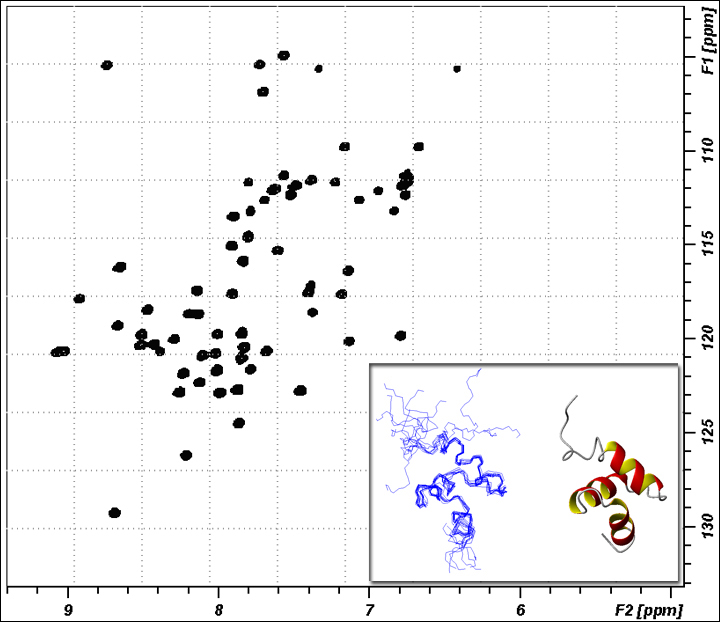
1H-15N HSQC (Tutorial link)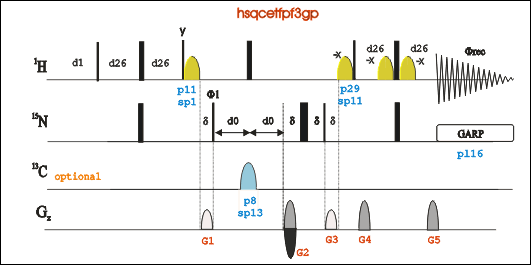
-
Go to an existing HSQC experiment (pulse program: hsqcetfpf3gp), type “edc” to copy its parameters and generate a new experiment number. Or in a new experiment number "rpar HSQCETFPF3GP".
-
Type “eda”, set parameters td, ns, ds, sw, O1P and O3P. For 13C and 15N labeled sample, ZGOPTNS should be "-DLABEL_CN".For only 15N labeled sample, leave ZGOPTNS blank.
-
Type “ased” to set power length and power level for both 1H and 15N, including p1, pL1, p21, pL21, pL12, and pcpd2. Or type "getprosol 1H A B" to set power related parameters. A is the pulse length in µs, and B is the power leverl in dB.
-
Estimate receiver gain using rga command, and Start the experiment using command zg;
-
Process the FID by typing “xfb”. Phase the spectrum when necessary.
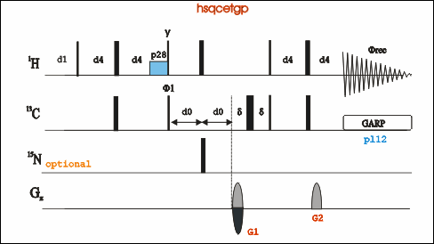
1H-13C HSQC
-
Go to an existing experiment (pulse program: hsqcetgp), type “edc” to copy its parameters and generate a new experiment number. Or in an new experiment number "rpar HSQCETGP".
-
Type “eda”, set parameters td, ns, sw, O1P and O2P, CNST2. Note that CNST2 can be different for different C-H bond.
-
Type “ased” to adjust power length and power level for both 1H and 13C, including p1, pL1, p3, pL2, pL12, and pcpd2. Or type "getprosol 1H A B" to set power related parameters. A is the pulse length in µs, and B is the power leverl in dB.
-
Start the experiment by rga and zg; Process the FID by typing “xfb”. Phase the spectrum when necessary.
1H-15N HET SOFAST (SOFAST-HMQC)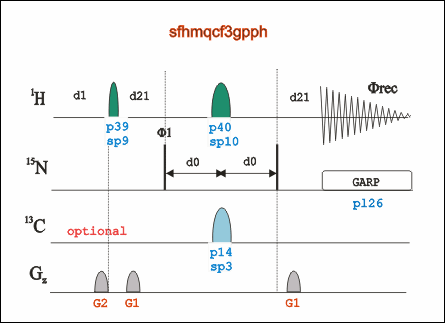
-
Go to an existing SOFAST experiment (pulse program: sofast), type “edc” to copy its parameters and generate a new experiment number. Or "rpar SFHMQCF3GPPH" in an new experiment entry.
-
Type “eda” to check and adjust parameters such as td, ns, sw, O1P and etc.
-
Type “ased” to adjust power length and power level for both 1H and 15N, including, pL1, p3, pL2, pL12, and pcpd2. Or type "getprosol 1H A B" to set power related parameters. A is the pulse length in µs, and B is the power leverl in dB.
-
To calibrate shape pulse sp15 and sp20, type “stdisp” to open shapetool window, and calculate PC9 (3000 us at 120°) and Reburp1000 (2000us at 180°) pulses. sp value = shapetool value + p1 in dB.
Shape Pulse Calculation Steps: choose the shape pule in shapte tool window, then go to Analysis/Integrate Shape, put in correct shape pulse length, angle, and 90 degree pulse length, hit "Enter" key. The calculated shapetool value will be shown as "Change of power level"
Note that for Bruker pulse programs, you may use "getprosol 1H pulselength powerlevel" command, to let TopSpin calculate the power related parameter for you.
- In the new Bruker SOFAST pulse programs (starting TopSpin 3.5), there are CNST54, and CNST55, which may be adjust to achieve better receiver gain RG.
-
Start the experiment by rga and zg;
-
Process the FID by typing “xfb”. Phase the spectrum when necessary.
2D TOCSY 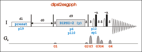
-
Go to an existing 2D-Tocsy experiment (pulse program: dipsi2esfbgpph), type “edc” to copy its parameters and generate a new experiment number. Or in a new experiment, "rpar DIPSI2ESFBGPPH".
Pulse program dipsi2esfbgpph is based on dipsi2esgpph and have f2 and f3 channels included.
-
Type "edasp" to check /adjust spectrometer routing.
-
Type “eda”, set parameters td, ns, ds, sw, O1P, O2P and O3P if necessary.
-
In acquisition window, if sample is unlabeled, leave ZGOPTNS blank. If sample is N15 labeled, set ZGOPTNS "-DLABEL_N". If sample is N15 and C13 labeled, set ZGOPTNS "-DLABEL_CN".
-
Type “ased”, adjust power length and power level for 1H. If sample is labeled, you will need to check 15N and/or 13C power level and power length according. Or type "getprosol 1H A B" to set power related parameters. A is the pulse length in µs, and B is the power leverl in dB.
-
Type "pulse" to calculate pL10 based on targeting p6 value. Use p6 35 us.
-
Set d9 (Tocsy mixing time) 90 ms for a protein sample; set pL32 70dB for water presaturation
-
In gs mode, adjust O1P and p12 to achieve minimum FID area integral for water suppression.
-
Start the experiment by rga and zg.
-
Process the FID by typing “xfb”. Phase the spectrum when necessary.
2D NOESY 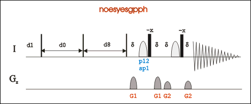
-
Go to an existing 2D-Noesy experiment (pulse program: noesyesfbgpph), type “edc” to copy its parameters and generate a new experiment number. Or in a new experiment, "rpar noesyesfbgpph".
*Pulse program noesyesfbgpph is based on noesyesgpph and have f2 and f3 channels included.
-
Type "edasp" to check and adjust spectrometer routing.
-
Type “eda”, set parameters td, ns, ds, sw, O1P, O2P and O3P if necessary.
-
In acquisition window, if sample is unlabeled, leave ZGOPTNS blank. If sample is N15 labeled, set ZGOPTNS "-DLABEL_N". If sample is N15 and C13 labeled, set ZGOPTNS "-DLABEL_CN".
-
Type “ased”, adjust power length and power level for 1H. If sample is labeled, you will need to check 15N and/or 13C power level and power length according. Or type "getprosol 1H A B" to set power related parameters. A is the pulse length in µs, and B is the power leverl in dB.
-
Set d8 (NOESY mixing time) around 90 ms for biomolecules, or 300-500 ms for small molecules; set pL32 70dB for water presaturation.
Users may consider using 2D-ROSEY for medium size molecules, MW 1000-3000 Da, mixing time 200ms. -
In gs mode, adjust O1P and p12 to achieve minimum FID area integral for water suppression.
-
Start the experiment by rga and zg.
-
Process the FID by typing “xfb”. Phase the spectrum when necessary.
Triple Resonance Experiments
Your may copy a data set from "expts" folder, or use rpar command to import a paramenter set from the bruker library.
Make sure the constants (cnst21, cnst22, cnst23) are set consistently through out all your 3D Triple resonance experiments, and also set O2P the value suggested in the pulseprogram. If one constant is different from one experiment to another, the resulting spectra may show discrepancy in carbon chemical shift of the same signal. Note that that discrepancy may not be correctable.
It is highly recommended to run a 2D 1H-13C plane of the 3D experiment first, just to make sure all the paramenters are set correctly. Signals in HNCA, HNCOCA, HNCACB, and CBCACONH should overlap well. Signals in HNCO and HNCACO should overlap well.
To process 3D data, check Fourier Transform REVERSE settings by looking at the processed 2D plane. Sometimes the default "FALSE" setting can be wrong resulting in a reversed spectrum. In general the 2D plane should be extracted and processed first, and then the optimized processing parameters are used to process the 3D data.
Reference values: CNST21=173, CNS22=53, CNST23=42
Saturation Transfer Difference (STD) - NMR experiment procedure
- DNA sample alone. For reference spectrum only, so low concentration is OK.
- Ligand sample alone.For reference spectrum only, so low concentration is OK.
- DNA+Ligand. Suggested molar ratio =<1:20, such as 0.1mM:2mM.
* All samples should have the same buffer composition. - Run standard proton 1Ds on all three samples. The spectrum of ligand alone should closely match the spectrum of DNA+ligand, since in the latter sample ligand is in large excess.
- Have sufficient number of scans (ns) to see all signals, especially for DNA signals in sample c.
- The reference spectra will give you an idea the distribution of ligand and DNA signals. Since ligands are usually small, their signals are fewer. Therefore, it is usually not difficult to select a DNA signal for irradiation (on resonance frequency), which should be far from ligand signal positions.
- Set up STD experiment for sample 3 (DNA+Ligand).
- Create a new data set, then “rpar STDDIFFESGP.3”. This is a STD experiment with water suppression by excitation sculpting pulse.
- Use command “getprosol 1H XX XXX” to set up all the pulse parameters.
- Check O1p, which may not be at 4.7 if organic solvent is in the buffer system.
- Saturation time D20 =2s by default. May need adjustment if necessary.
- SPW9 40-60dB. My experience is that 40dB worked better than 60dB.
- Number of scans ns should be high, >=64
- Create an irradiation frequency list and save in AcquPars/FQLIST/FQ2LIST, to define the irradiation frequency (on resonance frequency). The frequency should be on a DNA proton signal which is NOT close to any ligand signals.
The FQ2LIST file should have three numbers, magnet frequency, on resonance frequency and off resonance frequency. - Run the STD experiment.
- Process the data using AU program “stdsplit”.
- The first 1D should look like a standard 1D, and the second one would show ligand signals if the STD experiment worked.
- If no ligand signals appeared after trying different irradiation frequencies, either the ligand may not interact with the host, or the affinity may be very strong. The strong affinity can be identified by comparing 1D spectra of the DNA alone with the DNA in the presence of the ligand.
The best application of STD-NMR is ligand/drug screening, to identify ligand(s) that interacts with the host from a compound pool (multiple compounds) . In this system, the host is usually larger molecules, such as proteins and nucleic acids.
Samples: (using a DNA sample and one ligand as an example)
NMR Procedure:
NMR result:
Experiment Setup on NMR600 with a BBFO Probe
1H-15N HSQC. Set channel F2 instead of F3 to 15N. Use Bruker dataset HSQCETGP_15N (rpar HSQCETGP_15N) or modify a 13C HSQC experiment.
BBFO Probe Experiment library. Users can use those experiments as templates to set up their own experiments.
- 1D fluorine experiments are saved under /TopSpin3.2/data/expts/BBFO_19F folder.
- 2D experiments that have been tested for the BBFO probe are saved under /TopSpin3.X/data/expts/BBFO_2D folder. .
The BBFO probe has only two coils (two channels). One is designated to 1H, and and the other is adjustable to various nuclei from 15N to 31P. Therefore, the BBFO is limited to 1D and 2D expeirments.
Non-Uniform Sampling (NUS)
Data Acquisition, Run 'nusPGSv3' for better data point sampling! Note that the script won't work in a NMR folder that its name has a gap or space in it.
- In TopSpin AcquPars window, change the FnTYPE to be 'non-uniform_sampling'. You don’t need to set anything in the NUS parameters block.
- Type 'nusPGSv3' to create a data sampling schedule. Several questions will be asked along the way.
- Random Seed
- - 0 is default and probably what you want.
- - 0 implies the random seed used for random number generation will be selected by the computer.
- - Any other number here means you will also get the same sequence. So lets say you want to compare two acquisitions but are not interested in the differences that might result from sampling differently.
- Sine portion for sampling
- - 2 is default and probably what you want.
- - This is not the place to describe what this means. 2 will result in more points towards the front of the schedule and this is probably best for you. 1 and 0 are experimental and we don't suggest you use them unless you know why you want to.
- Number of points to collect (complex points)
- - When set 128 out of 1280, it is 10% sampling amount. 10% of the current numbers of linear, complex points is selected by default.
- - When running a 2D experiment, you probably want this to be more like 25%. 10% of all the complex points should work for a 3D experiment. 1-2% should work for a 4D. Note that the number you put in here is the total number of points to be sampled, not the percentage.
- Tolerance (as a percentage).
- - 0.01 % is the default. This means the generator must generate the number of points requested above +/- 0.01%. Most likely this means it will generate exactly the number you asked. Sometimes it is hard for the scheduler to find the exact number of samples you ask for so you may need to add some tolerance here. Try changing it to 10%.
- Shuffle the schedule (0 = no, 1 = yes)
- - Default is 0 which means the schedule will be generated with the left most column being "fast" and the right most column being the slowest. I suggest this for starting out.
- - Select 1 will shuffle the schedule. It is perfectly fine to do this as the reconstruction processing will reorder everything in the end anyway. However, note that the first point, (0 or 0,0 or 0,0,0) will always remain at the top.
- - At the end there should be a message” Poisson gas sampling schedule setup finished.”. A nusPGS_setup.out file will be generated into the data directory.
- Collect data with the 'zg' command. The schedule used will be deposited into the data directory with the name 'nuslist'. You can use this schedule as is during reconstruction with hmsIST.
NUS data processing
To process the spectrum, go to ProcPars page, and at NUS section, set MDD_mod to either cs or mdd (cs may give better result).
- 2D data processing (TopSpin 3.6 and above, does not require a NUS license)
- Type 'efp' and phase the 1D spectrum. Most likely only PHC0 needs to be adjusted.
- Copy the phasing parameter of the 1D (PHC0) to the 2D. You may or may not need to add 90 degree to the PHC0 depending on the experiment type. Trial and error!
- 2D HSQC: PHC0 in 2D = PHC0 in 1D +90
- 2D TOCSY: PHC0 in 2D = PHC0 in 1D
- Phase the 2D spectrum using 'xfb' command
- 3D data processing
- TopSpin method (Requires a TopSpin NUS license)
The workflow is to extract a 2D plane from the NUS 3D data, and then extract the first row 1D from the 2D plane. Phase the 1D spectrum and obtain its phase parameters. Apply the phase parameters to 2D and adjust PHC0 if necessary to obtain a good 2D spectrum. After that copy the 2D phase parameters to the 3D data, and process the 3D data.
- Open the 3D NUS data set, type 'rser2D' to “Extract a raw plane”. By default a new 2D data set will be generated as expt # 999.
- At the 2D data set, expt# 999, type 'efp' to process the first FID, which has the process number 999 set by default.
- Phase the 1D spectrum, and record its phase parameters, PHC0 in particular.
- Copy the 1D phase parameter(s) to the 2D data set and process the 2D data.
- Add 90 to the copied PHC0 value in 2D and then type 'xfb' to process the 2D data. Signals in the 2D spectrum should have the correct phase. If not, removed the added 90 in PHCO and process the data again.
- If the NUS 2Dspectrum does not match a regular 2D HSQC spectrum of the sample, very likely you need to set REVERSE of F1 to "TRUE" in the PROCPARS window and re-process the data again.
- Copy the 2D phase parameters and the REVERSE setting if changed to the 3D data set, and process 3D using the command 'ftnd'. “0” should be the option in the pop-up window.
- The 3D data processing may take a few minutes to finish, while its progress is shown at the left bottom corner of the TopSpin window. After it is done, to view 2D planes of the 3D spectrum, use the + , -, or the two way vertical arrow button to move the 2D plane.
- Restart or close TopSpin to release the floating license on your computer
- nmrPipe methods. https://www.ibbr.umd.edu/nmrpipe/nus.html, or http://gwagner.med.harvard.edu/intranet/hmsIST/234Proc.html.


